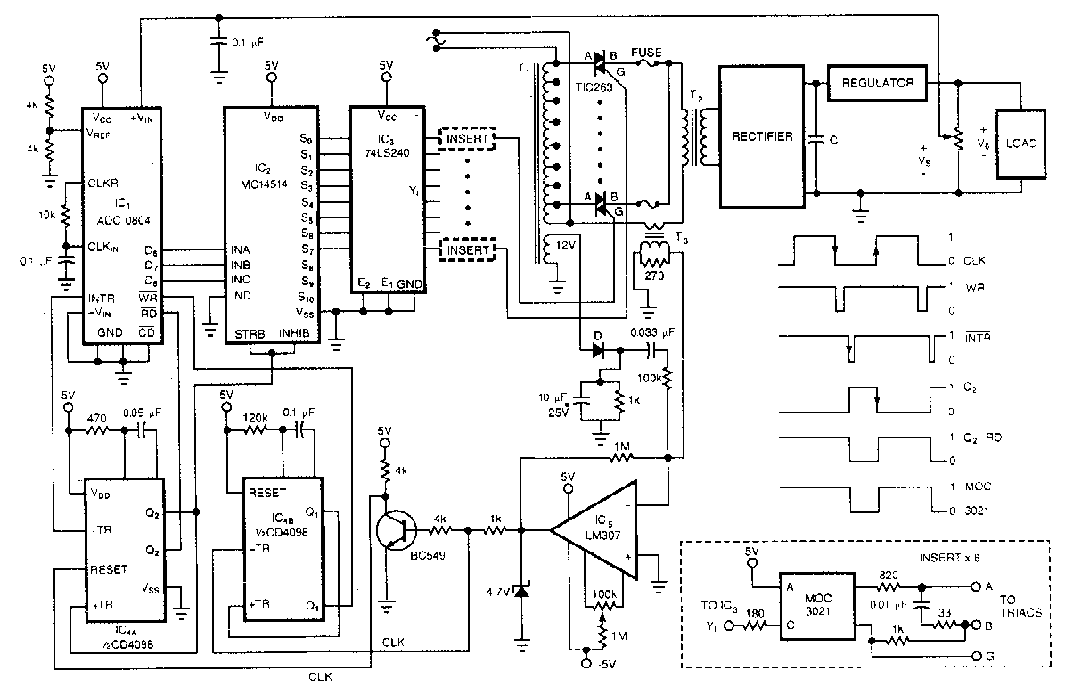
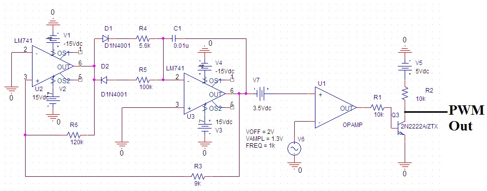
Pwm schematic circuit pulse modulation width figure 1 – 9v variable desktop power supply Pwm voltage module circuit diagram v1 codrey
To the Rails: April 2011
Saros electronics: october 2011
Linear power supply
Circuit pwm mosfet schematic channel driving motor protect when using dc result test automotive pump electrical electronicsPwm to voltage module (v1) Some power pwm drivers for electric dc motors13.8v 20a linear power supply circuit and explanation.
Help with creating a power supply555 timer pwm generator circuit diagram Regulated power supply schematicElectronic – voltage to pwm circuit, need to understand frequency.

Supply regulated voltage
Circuit schematics0-30v variable power supply circuit diagram at 3a Dc 30v eleccircuit voltage constant flow psuTo the rails: april 2011.
Operational amplifierOnly wiring and diagram: december 2013 Pwm 555 circuit timer generator diagram ic using circuits pulse modulation width generation signal led generate circuitdigest basic electronic boardCircuit pwm signal 12v 5v current schematics microcontroller diagrams amplification convert higher controlling fertilizer mosfets duty drop heavy motor drive.

October larger click
Power supply 20a circuit 8v linear diagram schematic explanationRegulated circuit Power supply circuit diagramsPower supply circuit audio diagrams control schematic diagram amp 2way gif.
Pwm voltage circuitlabPre-regulated high voltage power supply circuit diagram Power supply circuit diagram desktop variable 9v dc converter pc using 1v schematic digital electronics simple 12v voltage ac computerPwm circuit dc drivers power electric layout picotech motors some gif.

Pwm circuit schematic
.
.


