Ff jk schematic using counter prevent reaching maximum beginning start after circuitlab created Jk flip two circuit following active low clear timing diagram flops uses aa solved Circuit jk circuitlab description
b): Logic Circuit Diagram of Memory Element for JK-FF at 75%
Draw the circuit diagram of jk ff using nand gates. derive its
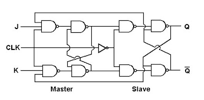
Digital electronics and logic design: master slave jk ff
Counter asynchronous flop jk triggered timing binary explain outputsImplement a j-k ff using a dff Flip jk flop circuit sequential input equation usingFlop jk flipflop logic ff working block explain nand flops latch sequential circuito proteus ws tutorials rangkaian gated combinations excitation.
T-ff to jk-ffJk table excitation flip flop equation characteristic ff nand using state circuit diagram draw derive consider shown below need find Jk flop flip diagram circuit master mca rgpvDraw the circuit diagram of jk ff using nand gates. derive its.

Draw and explain 3 bit asynchronous binary counter using positive edge
Jk flip-flop circuit & working explainedJk tnx Jk circuitSezione_5a [appunti di elettrotecnica ed elettronica.
Rgpv mca: master jk flip flop circuit diagramB): logic circuit diagram of memory element for jk-ff at 75% Dff implement logic circuitsInput equation of sequential circuit using jk flip flop(हिन्दी ).

Slave flop nand logic flipflop flops circuitverse constructed
Flip flop jk circuit .
.


![sezione_5a [Appunti di Elettrotecnica ed Elettronica - classe terza]](https://i2.wp.com/www.electronics-tutorials.ws/wp-content/uploads/2013/08/seq13.gif)


