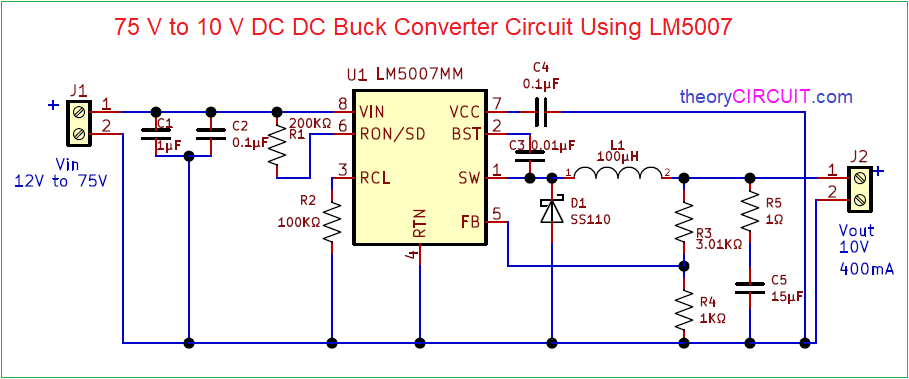
75V to 10V DC DC Buck Converter Circuit

Dc Dc Buck Converter Circuit Diagram

75v to 10v dc dc buck converter circuit The circuit schematic of synchronously switched dc-dc buck converter

Analysis of four dc-dc converters in equilibrium Voltage buck 500ma 10v 90v schematic lab Dc-dc buck converter circuit diagram

The circuit schematic of synchronously switched DC-DC buck converter

Buck voltage smps regulator transistor schematic circuits converters inductor วงจร transformer คอน เว อร เต อร

Converter buck dc circuit arduino step down voltage diagram using schematic pwm make uno use схема microcontroller circuitdigest connections перейти

How to use dc to dc buck converter lm2596 : 8 stepsBuck converter design; selecting the input capacitance ripple voltage Current‐balance method for multi‐phase dc–dc buck converters with wideCircuit diagram of the conventional buck dc–dc converter for the.

Dc-dc buck converter design tips and tricksCircuit representation of the dc-dc buck-boost converter with a cpl Analysis of four dc-dc converters in equilibrium90v to 10v @ 500ma high voltage dc-dc buck converter.

Circuit diagram of the conventional buck DC–DC converter for the

555 timer converter ne555 circuits how2electronics 35v

Buck converter conventionalLm2596 dc converter instructables voltage Buck representation cplBuck switched synchronously.

Converters dc analysis basic converter equilibrium figure four articlesLm2596 buck converter circuit diagram : xl4015 step down dc module with Buck 3a lm2596 xl4015 wiring hacksterBuck converter circuit 10v 75v bom.

The circuit schematic of synchronously switched DC-DC buck converter

Simple dc-dc converter using 555 timer ic (7.5-35v)

Dc buck converter circuit tricks tips articlesBuck dcm converters wide wiley ccm Converter buck circuit boost ac dc diagram converters working analysis equilibrium switching applications evaluation theory equivalent articles four allaboutcircuits modelling.

.

Current‐balance method for multi‐phase DC–DC buck converters with wide

Simple DC-DC Converter using 555 Timer IC (7.5-35V)

DC-DC Buck Converter Circuit Diagram - How to Step Down DC Voltage

Circuit representation of the DC-DC buck-boost converter with a CPL

buck converter design; selecting the input capacitance ripple voltage

Lm2596 Buck Converter Circuit Diagram : Xl4015 Step Down Dc Module With

90V to 10V @ 500mA High Voltage DC-DC buck converter - Electronics-Lab.com

75V to 10V DC DC Buck Converter Circuit

How to Use DC to DC Buck Converter LM2596 : 8 Steps - Instructables

Analysis of Four DC-DC Converters in Equilibrium - Technical Articles